Formulate an ER Diagram
Read This on Github
⭐ Make ER Diagram
Steps to make ER Diagram
-
Identify entities
- Determine the real-world objects or concepts that will be part of the system
- Entities should be able to be identified uniquely
-
Define attributes
- For each entity, define the properties or characteristics that describe it
- Attributes should be specific and relevant to the entity
-
Determine relationships
- Identify how the entities are connected and interact with each other
- Determine the type of relationship, such as one-to-one, one-to-many, or many-to-many
-
Draw the ER diagram
- Use boxes or rectangles to represent entities and their attributes
- Use lines or diamonds to represent the relationships between entities
-
Add points
- Include additional information about the entities or relationships as notes or points on the diagram
- Provide any constraints or rules that apply to the entities or relationships
-
Validate and refine the ER diagram
- Review the diagram to ensure it accurately represents the system being modeled
- Make any necessary changes or adjustments to improve the diagram's accuracy and usability.
⭐ Requirement Engineering
Requirements of Banking System
- Banking system → Branches
Bank may have multiple branches
- Bank → customers.
Bank has multiple customers
- Customers → accounts & take loans.
Customer may have multiple accounts & take multiple loans
- Customer associated with some banker.
Customer may be associated with multiple bankers means when you deal with loan you need manager or branch manager or some banker.
- Bank has employees.
Bank has multiple employees
- Account → Savings, Current, FD, RD, Loan Account
Account may be of multiple types like savings, current, FD, RD, Loan Account
- Loan originated by branch. loan = multiple customers → Payment schedulePayment schedule
Loan may be originated by multiple branches and multiple customers also have multiple payment schedules.
Payment schedule may be of multiple types like monthly, quarterly, half yearly, yearly.
⭐ Steps to Visualize
How to identify Entity & Attribute sets
We think this DB as bottom up approach. So we will start from weakest entity set and then we will move to strong entity set.
Step 1
Entity Sets
1. Branch2. Customer
3. Employee
4. Savings A/C (Account Entity Set) → Generalization
5. Current A/C (Account Entity Set) → Generalization
6. Loan
7. Payment (loan) → Weakest entity set
Step 2
Attributes
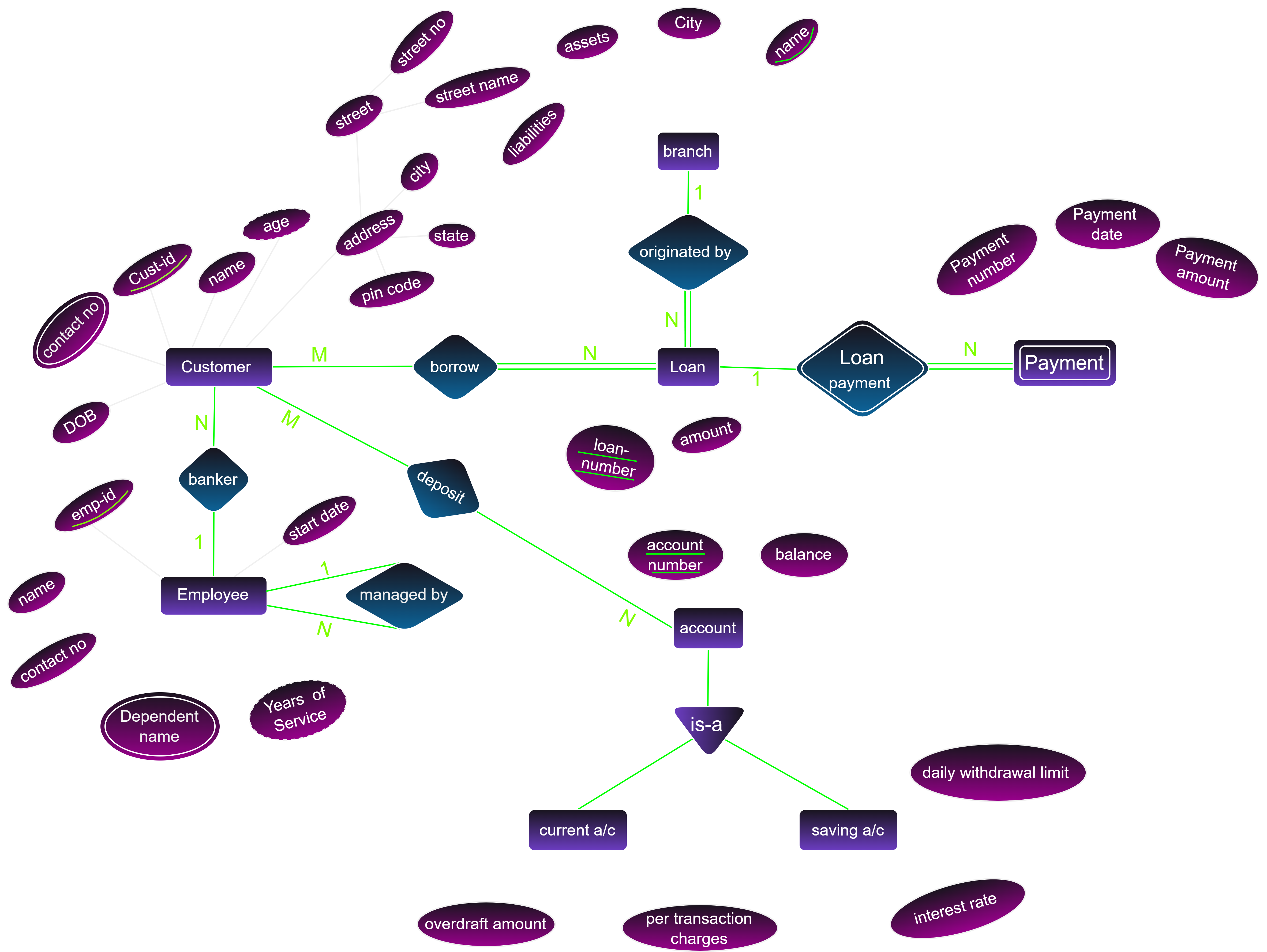
1.Branch → Branch ID, Branch Name (primary key), Branch Address, Branch Manager , Liability, Assets, City, State, Country
2. Customer → Cust-id (primary key), Name , Address(Composite Attribute) , Contact no(Multi Valued) , DOB , Age(Derived Attribute)
3. Employee → Emp-id (primary key), Name , Contact no(Single Valued) , Department Name(Multi Valued) , Years of Service (Derived Valued) , Start Date(Single Valued)
4. Savings A/C → Acc-Number(primary key) , balance , interest rate , daily interest limit
5. Current A/C → Acc-Number (primary key), balance , Per transaction charge , overdraft amount
6. Generalized Entity "Account" → Acc-No , Balance
We have generalized Account entity set because both Savings A/C and Current A/C have same attributes.
7. Loan → loan-number(primary key) , amount
8. Weak Entity "Payment" → payment-number , amount , date
Step 3
Relationships & Constraints
1. Customer & Loan
Mapping Cardinality- Customer
<borrow>Loan → many to many (M : N)
Participation ConstraintsCustomer can borrow multiple loans and loan can be borrowed by multiple customers.
loanandborrowis total participation constraint because if loan is exist then customer must be exist and vice versa.
2. Loan & Branch
Mapping Cardinality- Loan
<originated by>Branch → many to one (n : 1)
Participation ConstraintsLoan can be originated by only one branch and one branch can originate multiple loans.
loanandoriginated byis total participation constraint because if loan is exist then branch must be exist and vice versa.
3. Loan & Payment (weak relationship)
If we have a weak entity set in a database, and it participates in a relationship with another weak entity set, then this relationship is considered a weak relationship. To properly model this relationship, we should apply a total participation constraint to the weak entity set that participates in the relationship.
Mapping Cardinality- Loan
<has>Payment → one to many (1 : n)
Participation ConstraintsLoan can have multiple payments and payment can be associated with only one loan.
loanandhasis total participation constraint because if loan is exist then payment must be exist and vice versa.
4. Customer & Account
Mapping Cardinality- Customer
<depsit>Account → many to many (M : N)
Participation ConstraintsCustomer can deposit multiple accounts and account can be deposited by multiple customers.
accountanddepositis total participation constraint because if account is exist then customer must be exist and vice versa.
5. Customer & Banker
Mapping Cardinality- Customer
<associated with>Banker → many to one (N : 1)
Participation ConstraintsCustomer can be associated with multiple bankers and banker can be associated with multiple customers.
customerandassociated withis total participation constraint because if customer is exist then banker must be exist and vice versa.
6. Employee & Employee (Unary Relationship)
Mapping Cardinality- Employee
<managed by>Employee → many to one (N : 1)
Participation ConstraintsEmployee can be managed by multiple employees and employee can be managed by multiple employees.
employeeandmanaged byis total participation constraint because if employee is exist then employee must be exist and vice versa.